|
|
|
|
|

| |||||||||||||||||||||||||||||||||||||||||||||||||||||||||||||||||||||||||||||||||||||||||||||||||||||||||||||||||||||||||||||||||||||||||||||||||||||||||||||||||
|
Our Gateway Computers
Coza`s 233
| ||||||||||||||||||||||||||||||||||||||||||||||||||||||||||||||||||||||||||||||||||||||||||||||||||||||||||||||||||||||||||||||||||||||||||||||||||||||||||||||||||
| Part Number: MBDSAC152AAWW/2501349
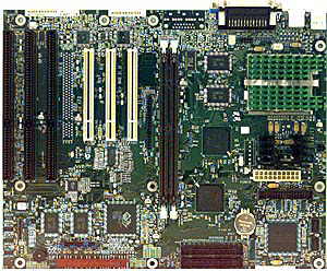
Jabil 586 233MHz PCI Motherboard With MMX And Integrated Video PCI Compliance - PCI 2.1 Form Factor - ATX Socket Type - 321-pin Socket 7 BIOS Revisions Memory Upgrades Processor and Processor Upgrades Hard Drive and Controller Information |
| |||||||||||||||||||||||||||||||||||||||||||||||||||||||||||||||||||||||||||||||||||||||||||||||||||||||||||||||||||||||||||||||||||||||||||||||||||||||||||||||||
| BIOS Information:
Important!: Make sure that your BIOS begins with 4L3TT0X0. Before making any changes to your BIOS, document your old CMOS settings so that when you update your BIOS, you'll have a record of the old settings. This is very important, so that you don't run into problems later on. Recovery Mode Procedure:
Memory Information
The two DIMM sockets are arranged as Bank 0 and Bank 1. Each bank consists of one socket and a 64-bit wide data path. Bank 0 only, Bank 1 only, or both banks may be populated. EDO and SDRAM may be installed in the same system. Only gold-plated DIMMs are to be used with this motherboard.
When upgrading the memory, there is no need to adjust any jumpers or switches. The system recognizes the additional memory upon boot-up. The system board recognizes which bank the memory resides in and what type it is.
Only unbuffered, 4-clock 3.3V SDRAM DIMMs are supported. Buffered, 5V, or 2-clock SDRAM DIMMs should not be used. This board does not support SDRAM DIMMs with an n x 4 DRAM base. For example, a DIMM that uses sixteen 16Mbit x 4 devices should not be used.
Memory Configuration Table
Processors and Upgrade Information
The 82430TX can support the following pentium processor speeds. Jumper block J9C1-C,D is used to configure the system board for the processor that is installed. These settings are also in your Technical Reference Manual that shipped with your computer.
This board can support the MMX Pentium Overdrive designed for the CPU that your computer shipped with from the factory.
Please keep in mind that the only CPU's authorized for use with your computer by Gateway 2000 are the processor that shipped with your computer or the MMX Pentium Overdrive that was designed for use with your original CPU speed with no modification to your motherboard. Therefore, by purchasing and installing one other than those recommended, you are acting on your own behalf and Gateway 2000 assumes no responsibility for support.
Hard Drive and Controller Information
This motherboard provides two independent bus-mastering PCI IDE interfaces that support PIO Mode 3 and Mode 4 devices. The system BIOS supports Logical Block Addressing (LBA) and Extended Cylinder Sector Head (ECHS) translation modes as well as ATAPI devices on both IDE interfaces. The system BIOS automatically detects IDE device transfer rate and translation mode. IDE hard drives up to 8.4 gig in size can be used on this motherboard and be automatically detected regardless of the BIOS version.
Normally, programmed I/O operations require a substantial amount of CPU bandwidth. In true multi-tasking operating systems like Windows 95, the CPU bandwidth freed up by using bus mastering IDE can be used to complete other tasks while disk transfers are occurring. When used in conjunction with the appropriate driver for the Windows 95 environment, the IDE interface can operate as a PCI master capable of supporting PIO Mode 4 devices with transfer rates of up to 16 MB/sec.
When hooking up the cabling to the IDE connectors, be sure to maintain pin 1 orientation. The red speckled edge on both of the ribbon cables faces the bottom of the case when the Integrated Pentium is configured into the ATX tower case. However, on the BATC convertible case, the red speckled edge faces in varied directions depending on the case configuration. | ||||||||||||||||||||||||||||||||||||||||||||||||||||||||||||||||||||||||||||||||||||||||||||||||||||||||||||||||||||||||||||||||||||||||||||||||||||||||||||||||||