BIOS Information:
Important!: Make sure that your BIOS begins with 4A4LL0X0.
Before making any changes to your BIOS, document your old CMOS settings so that when you update your BIOS, you'll have a record of the old settings. This is very important, so that you don't run into problems later on.
BIOS Update:
When BIOS update is complete, remove the disk from the floppy drive and press ENTER to restart the computer.
Updating computer settings If your computer contains a processor faster than 233 Megahertz (MHz), you must update the speed in the new BIOS.
Turn off the computer and remove the cover.
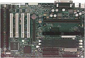
Locate jumper J8B2 in the front corner of the motherboard.
Move the jumper from the normal 1-2 pin position to the 2-3 pin position.
The 2-3 pin setting initiates a BIOS maintenance mode that lets you set the processor speed.
Turn on the computer to enter Maintenance Mode and set the processor speed.
Once the processor speed has been set and the configuration has been saved, turn off the computer and replace the J8B2 jumper to the 1-2 pin position.
Restart the computer and the new processor speed is displayed.
Enter the new BIOS and verify the setting are the same as those you copied down earlier.
Memory Information
The motherboard has three Dual Inline Memory Module (DIMM) sockets.
Minimum memory size is 8 Megabytes (MB); maximum size is 384 MB.
The BIOS automatically detects memory type, size, and speed.
The motherboard supports the following memory features:
168-pin DIMMs with gold-plated contacts 66 MHz SDRAM only.
Synchronous DRAM improves memory performance through memory access that is synchronous with the memory clock.
This simplifies the timing design and increases memory speed because all timing is dependent on the number of memory clock cycles.
The SDRAM should also meet the Intel 4-clock, 66 MHz, unbuffered SDRAM specifications.
Memory Error Checking and Correction (ECC) is a powerful feature designed to detect memory errors as they occur without interrupting computer operation.
ECC memory detects multiple-bit errors when two or more bits have failed, and corrects single-bit errors when a single bit has failed.
When ECC memory is installed, the BIOS supports both ECC and non-ECC mode.
ECC mode is enabled in the setup program.
The BIOS automatically detects if ECC memory is installed and provides the setup option for selecting ECC mode.
Non-ECC (64-bit) and ECC (72-bit) memory 3.3V memory only Single or double-sided DIMMs
| Memory Configuration Table
| | DIMM Size
| Non-ECC Configuration
| ECC Configuration
| | 8 MB
| 1 Mbit x 64
| 1 Mbit x 72
| | 16 MB
| 2 Mbit x 64
| 2 Mbit x 72
| | 32 MB
| 4 Mbit x 64
| 4 Mbit x 72
| | 64 MB
| 8 Mbit x 64
| 8 Mbit x 72
| | 128 MB
| 16 Mbit x 64
| 16 Mbit x 72
|
Note: Memory can be installed in one, two, or three sockets.
Memory size and speed can vary between sockets.
Bank 0 is toward the front of the board.
Processors and Upgrade Information
The motherboard currently supports a processor that runs internally at 233 MHz, 266 MHz, 300 MHz, and 333 MHz with 512 KB second-level (L2) cache.
Hard disk and controller information.
This board provides two independent bus-mastering PCI IDE interfaces that support PIO Mode 3, Mode 4 and Ultra ATA devices.
The computer's BIOS supports Logical Block Addressing (LBA) and extended Cylinder Sector Head (ECHS) translation modes as well as ATAPI devices on both IDE interfaces.
The computer's BIOS automatically detects IDE device transfer rate and translation mode.
The current BIOS will support an IDE hard disk up to 8.4 GB in size that is connected to the onboard IDE controllers.
The drives will automatically be detected upon startup.
Normally, programmed I/O operations require a substantial amount of CPU bandwidth.
In true multi-tasking operating systems like Windows 95, the CPU bandwidth freed up by using bus mastering IDE can be used to complete other tasks while disk transfers are occurring.
When used in conjunction with the appropriate driver for the Windows 95 environment, the IDE interface can operate as a PCI master capable of supporting Ultra ATA devices with transfer rates of up to 33 MB/sec.
When hooking up the cabling to the IDE connectors, be sure to maintain pin 1 orientation.
The red speckled edge on both of the ribbon cables faces the bottom of the case when the Integrated Pentium is configured into the ATX tower case.
However, on the BATC convertible case, the red speckled edge faces in varied directions depending on the case configuration.
|