Atapi Connections
The audio connectors include the following:
The audio connectors include the following:
ATAPI CD-ROM audio connector (black)
ATAPI style telephony header (green)
ATAPI style line in header (natural/white)
The ATAPI CD-ROM audio connector (black) and the ATAPI style telephony header (green) are located to the left of the MIDI/Game port.
The ATAPI style line in header (natural/white) is located to the left of the ATAPI CD-ROM audio connector (black) and the ATAPI style telephony header (green).
Battery
This illustration is a closer view of the coin cell style battery which provides power to the RTC (Real-Time Clock) and CMOS SRAM memory.
When the system is plugged in, the 3.3 V standby current from the power supply extends the life of the battery.
The clock provides a time-of-day clock and a multicentury calendar with alarm features and a century rollover.
It also supports 256 bytes of battery-backed CMOS SRAM in two banks reserved for BIOS use.
The RTC is accurate to � 13 min/year at 25�C with 3.3 VSB applied.
The time, date and SRAM values can be specified and returned to their defaults in the Setup program.
Bios
The system board uses an Intel/Phoenix BIOS which is stored in Flash EEPROM and can be easily upgraded using a disk-based program.
In addition to the Intel/Phoenix BIOS, the Flash EEPROM also contains the Setup utility, Power-On Self Tests (POST), Advanced Power Management (APM), update recovery code, the PCI auto-configuration utility and Windows 95 Plug-N-Play code.
A new version of the BIOS can be installed from a diskette using the IFlash Update utility.
The disk-based IFlash upgrade utility, IFLASH.EXE, has three options for BIOS upgrades:
The Flash BIOS can be updated from a file on a diskette
The current BIOS code can be copied from the Flash EEPROM to a disk file as a backup in the event that an upgrade cannot be successfully completed.
The BIOS in the Flash device can be compared with a file to ensure the system has the correct version.
The upgrade utility ensures the upgrade BIOS extension matches the target system to prevent accidentally installing a BIOS for a different type of system.
Different languages may be selected for the setup utility (CMOS) using the BIOS update utility.
The current BIOS for this system can be found here.
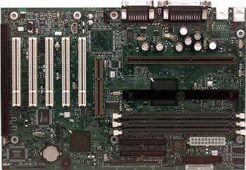
DIMM Configuration
The motherboard has three Dual Inline Memory Module (DIMM) sockets. Minimum memory size is 8MB; maximum size is 384MB.
The BIOS automatically detects memory type, size, and speed. Memory can be installed in one, two or three sockets.
Memory type, size and speed can vary between sockets. Bank 0 is toward the back of the board, next is bank 1, then bank 2.
168-pin DIMMs with gold-plated contacts Unbuffered SDRAM
Synchronous DRAM improves memory performance through memory access that is synchronous with the memory clock.
This simplifies the timing design and increases memory speed because all timing is dependent on the number of memory clock cycles.
The SDRAM should also meet the PC SDRAM Unbuffered DIMM Specification for either 64-bit or 72-bit SDRAM.
Memory Error Checking and Correction (ECC) is a powerful feature designed to detect memory errors as they occur without interrupting system operation.
ECC memory detects multiple-bit errors (when two or more bits have failed) and corrects single-bit errors (when a single bit has failed).
When ECC memory is installed, the BIOS supports both ECC and non-ECC mode.
ECC mode is enabled in the setup program.
The BIOS automatically detects if ECC memory is installed and provides the setup option for selecting ECC mode.
66 or 100MHz SDRAM only
Processors with a 100MHz FSB should only be used with 100MHz RAM.
Processors with a 66MHz FSB can be used with 100 or 66MHz RAM.
Non-ECC (64-bit) and ECC (72-bit) memory 3.3V memory only
Single or double-sided DIMMs in the following sizes:
DIMM Size Non-ECC Configuration ECC Configuration
| DIMM Size
| Non-ECC Configuration
| ECC Configuration
| | 8MB
| 1 Mbit x 64
| 1 Mbit x 72
| | 16MB
| 2 Mbit x 64
| 2 Mbit x 72
| | 32MB
| 4 Mbit x 64
| 4 Mbit x 72
| | 64MB
| 8 Mbit x 64
| 8 Mbit x 72
| | 128MB
| 16 Mbit x 64
| 16 Mbit x 72
|
Floppy Connection
This is the floppy connector present on the motherboard.
The floppy drive connector is located to the right of the IDE connectors.
When hooking up the cabling to the floppy connector, be sure to maintain pin 1 orientation.
The red speckled edge on the ribbon cable faces the bottom of the case when the system board is configured into the ATX tower case.
In the illustration, the red speckled edge will be on the left side.
The connector is also keyed, although some cables may not be.
In the BIOS setup, the floppy interface can be configured for:
360 KB or 1.2 MB 5 1/4" media 720 KB, 1.2 MB, 1.44 MB, or 2.88 MB 3 1/2" media
Configuring the floppy interface for 1.2 MB 3 1/2" (3-mode floppy) requires the use of special floppy drives and a driver for the specific operating system.
The I/O controller is software compatible with the 82077 floppy drive controller and supports both PC-AT and PS/2 modes.
This system board includes LS-120 support
IDE Connections
These are the IDE connectors present on the motherboard.
The PCI IDE connectors are labeled SEC IDE (top) and PRI IDE (bottom).
The floppy drive connector is located to the right of the IDE connectors.
The motherboard provides two independent bus-mastering PCI IDE interfaces that support PIO Mode 3, Mode 4 and Ultra ATA (synchronous DMA mode transfer) devices.
The system BIOS supports Logical Block Addressing (LBA) and Extended Cylinder Head Sector (ECHS) translation modes as well as ATAPI devices on both IDE interfaces.
The system BIOS automatically detects IDE device transfer rate and translation mode.
Normally, programmed I/O operations require a substantial amount of CPU bandwidth.
In true multi-tasking operating systems the CPU bandwidth freed up by using bus mastering IDE can be used to complete other tasks while disk transfers are occurring.
When used in conjunction with the appropriate driver, the IDE interface can operate as a PCI master capable of supporting Ultra ATA devices with transfer rates of up to 33 MB/sec.
When hooking up the cabling to the IDE connectors, be sure to maintain pin 1 orientation.
The red speckled edge on both of the ribbon cables faces the bottom of the case when the system board is configured into the ATX tower case.
In the illustration above, the red speckled edge will be on the left side.
The connectors are also keyed, although some cables may not be.
I/O Ports
The I/O connections present on the motherboard.
The ports are integrated into the motherboard.
There are no separate cables that connect the ports to the motherboard.
The I/O panel features two PS/2 ports, two USB (Universal Serial Bus) connectors, one parallel port, two serial ports, a MIDI/Game port and audio connectors.
PS/2 Keyboard and Mouse Interface
PS/2 keyboard and mouse connectors are located on the back panel of the motherboard.
The +5V lines to these connectors are protected with a PolySwitch circuit which acts like a self-healing fuse, re-establishing the connection after an over-current condition is removed.
While this device eliminated the possibility of having to replace a fuse, care should be taken to turn off the system power before installing or removing a keyboard or mouse.
The keyboard and mouse may be plugged into either connector.
The keyboard controller contains the keyboard and mouse controller code, provides the keyboard and mouse control functions, and supports password protection for power on/reset.
A power on/reset password may be specified in the CMOS Setup program.
The keyboard controller also supports the hot-key sequence Ctrl+Alt+Del for a software reset.
This key sequence resets the computer's software by jumping to the beginning of the BIOS code and running the Power-On Self Test (POST).
USB - Universal Serial Bus
The motherboard has two USB ports;
one USB peripheral may be connected to each port.
Port 0 is on top, port 1 on the bottom. For more than two USB devices, an external hub may be connected to either port.
Some devices may even have a throughput on the plug.
The motherboard fully supports the Universal Host Controller Interface (UHCI) and uses UHCI-compatible software drivers.
USB features include:
Self-identifying, hot pluggable peripherals
Drivers will not have to be loaded and the system will not have to be reconfigured or rebooted.
After plugging the USB peripheral into the USB port, the peripheral automatically becomes fully functional.
Automatic mapping of function to driver and configuration
Support of isochronous and asynchronous transfer types Support for 127 physical devices (as long as the cumulative bandwidth demands do not exceed 12 Mbps)
This is roughly 100 times the limit of current serial busses and is wide enough to daisy-chain a printer, scanner, still camera, and removable hard drive from one port.
Guaranteed bandwidth and low latencies appropriate for telephony, audio, and other applications
Error handling and fault recovery mechanisms built into protocol
USB keyboards and mice are supported as legacy devices during boot and under operating systems without USB support.
Note: Computers that have an unshielded cable attached to a USB port may not meet FCC Class B requirements, even if no device or a low speed USB device is attached to the cable.
Use shielded cable that meets the requirements for full speed devices.
Parallel Port
A 25-pin D-sub header is provided on the back panel for a multi-mode, bi-directional port.
The parallel port operates in Compatible (standard mode), Bi-directional (PS/2 compatible), Enhanced Parallel Port (EPP) and a high speed Extended Capabilities Port (ECP) mode.
EPP Mode requires a driver provided by the peripheral manufacturer to operate correctly. The parallel port can be configured in CMOS.
Serial Ports
Two integrated 9-pin serial connectors are provided on the back panel.
The 16450 and 16550A compatible UARTs support data transfers at speeds up to 115.2Kbits/sec (in extended UART mode).
Both of these ports can be configured in several different combinations in the CMOS Setup.
Processor Support
This motherboard supports one Pentium II/III processor.
The processor's Voltage Identification (VID) pins automatically program the voltage regulator on the motherboard to the required processor voltage.
The motherboard currently supports processors that are compliant with the VRM 8.2 DC-DC Converter Design Guidelines document.
This is the specification that defines DC-to-DC converters to meet the power requirements of the Intel Pentium II processor and future microprocessors.
Note: This motherboard supports Pentium II processors with a 100 or 66MHz front side bus (FSB).
Processors with a 100MHz FSB should only be used with 100MHz RAM.
Processors with a 66MHz FSB can be used with 100 or 66MHz RAM.
Processor Upgrades The motherboard can be upgraded with Pentium II processors that run at higher speeds by using the configure mode in CMOS.
System Jumper
The system configuration jumper block (J7B1) requires a single jumper to set the configuration mode for the Setup program.
This allows for all motherboard configuration to be done in Setup, including processor speed and bus frequency.
Do not move this jumper with the system power on.
System Configuration Jumper Settings
Normal Mode
This mode is for normal computer booting and operations.
Connect pins 1 and 2 with a jumper to enable the mode.
The BIOS uses the current bus/processor frequency ratio, configuration information, and passwords to boot the computer.
Access to the Setup program can be restricted using a supervisor or user password.
In normal mode, the BIOS attempts an automatic recovery if the configuration information in flash memory is corrupted.
Configure Mode
This mode is for configuring the processor speed and clearing passwords.
Connect pins 2 and 3 with a jumper to enable the mode.
In this mode, Setup automatically executes after the POST runs, and no password is required.
Setup provides the maintenance menu with options for setting the processor speed and clearing passwords.
All other Setup screens are also available.
Configure mode uses the default BIOS settings for booting, not the current user or supervisor settings.
The default settings include the lowest bus/processor frequency ratio the processor supports.
When the computer is rebooted, Setup uses the original user and supervisor settings with the exception of the options that were changed.
For the configuration changes to take effect after exiting the Setup program, power down the computer, set the configuration jumper to normal mode and boot the computer.
In configure mode, the BIOS attempts an automatic recovery if the configuration information in flash memory is corrupted.
Recovery Mode
This mode is for recovering BIOS data.
Remove the jumper (no pins connected) from the configuration jumper block to enable this mode.
After the computer is powered on, the BIOS attempts to upgrade or recover the BIOS data from a diskette in the floppy drive.
If the recovery fails with a diskette in the boot drive, a beep code indicates that the recovery failed.
If a diskette is not in the boot drive, the BIOS attempts to run the POST, does not boot the operating system and displays a message that the jumper is not properly installed.
For the configuration changes to take effect after a successful recovery, power down the computer, set the configuration jumper to normal mode and boot the computer.
LS-120 Support
LS-120 technology (the LS stands for laser servo) uses a unique manufacturing process to increase the data track density on a 3.5" diskette from 135 tracks per inch (tpi) to 2490 tpi.
Imagine moving the grooves in an old-fashioned record album much closer together so you could record a lot more music on the same album.
This is similar to what the LS-120 technology does.
A laser servo motor positions the LS-120 drive's read/write head precisely over the correct track on the diskette for accurate data reading/writing.
That's why so many people in the computer industry believe the technology will replace the 1.44 megabyte (MB) diskette in new computers.
NOTE: SuperDisk LS-120 diskettes require a special LS-120 drive; they cannot be read or written in 1.44MB drives.
Key features of the LS-120 technology include the following:
Enables users to store 120MB of data on a single, 3.5" diskette.
Represents a capacity increase of more than 83 times over the standard 3.5" diskette.
Is completely backward compatible with the installed base of over 10 billion 3.5" diskettes.
It reads and writes 1.44MB and 720K DOS-formatted diskettes as well as the new 120MB format.
The technology also includes embedded support under the Windows 95 (OSR2) and Windows NT 4.0 operating systems.
Delivers up to five times the performance of standard 1.44MB diskette technology, significantly increasing user productivity.
Users can:
Transport large files on a single diskette.
Download and save internet and network information.
Store large or multiple work-in-progress files on a single diskette.
Save color, sound and motion files without compression.
Store and retrieve fax images, E-mail and phone messages.
Save hard disk space.
Store multiple program files for a single project on one diskette.
While the SuperDisk LS-120 diskettes and drives look much the same as the standard 1.44MB diskettes and drives, the technical differences are substantial.
Below is a comparison of key specifications:
LS-120 Technology Standard Technology Formatted capacity 120 MB vs. 1.44 MB
Transfer rate: Parallel port 290 KB/sec vs. 45 KB/sec
Internal IDE 484 KB/sec
Average Seek Time 70 msec vs. 84 msec
Disk Rotational Speed 720 rpm vs. 300 rpm
Track Density 2,490 tpi vs. 135 tpi
Number of tracks 1,736 X 2 sides vs. 80 X 2 sides
|